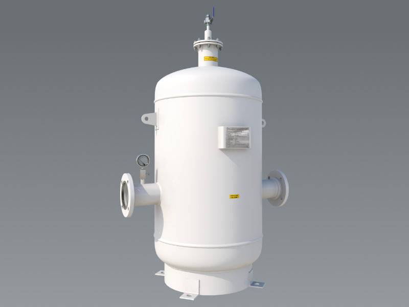
Cryogenic offers Air Eliminators for variety of installations and conditions and designed for separation, Elimination of air from the Liquid. without allowing the contained liquid to escape.
Positive Displacement meter, is a volumetric measuring device can not differentiate between liquid, air and vapor. So when liquid enters with air or vapor into this measuring devices it will contribute the measurable error.
Large amount of free air or vapor entrapped in the piping system, not only compromising meter accuracy but also lead to over speeding of meter and also creating excessive wear or unit failure.
To ensure accurate liquid Measurement, it is necessary to remove all air from the system before entering into the measuring devices.
Hence Air Eliminator is installed before the meter for accuracy of the measurement devices. We also offers Split type Air Eliminators for fuels like Aviation Turbine Fuel where frequent clearing is required.
We offer Air Eliminators from 25 ltrs to 6000 ltrs with size of 1.5" to 24" with 150# to 600# with design as per ASME Section VIII div I.
We have credit of supplying a more than 2100 units by 2014.
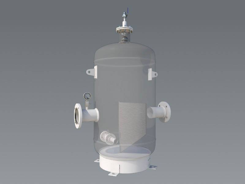
Air Eliminator consists of top nozzle housing with float assembly which is made up of float and guide rod. Now when product is entered into air eliminator which consists of air / vapor through inlet nozzle it enters into large open vessel area which decrease the velocity of the fluid and try to bring liquid to the stable state and as flow strike to the baffle plate which separates liquid and air / vapor which again travel to the top of the vessel and release through the float assembly. Now when air is released and further liquid level is rise up to float assembly will push this assembly up and close the orifice area.
Now when more air is coming into the system or vapor is generated it will again travel to the top and accumulate in the top housing and at a certain stage when collected air /vapor forces liquid level down, buoyant force acting on the float reduces, this will reduce float buoyancy and float drops down which allows air / vapor to escape through the seat orifice. Now as fluid replaces air, Float buoyancy again increases and allowing float to rise and close to orifice seat.
We also offers Split type Air Eliminators for fuels like Aviation Turbine Fuel.
We offer Air Eliminators from 25 ltrs to 6000 ltrs with size of 1” to 24” with 150# to 600# with design as per ASME Section VIII div I.
We have credit of supplying a more than 3000 units by 2018.
| SIZE | A END TO END DIMENSION |
B NOZZLE ELEVATION |
C DIAMETER |
D END TO END WITH DRAIN VALVE |
E TOTAL HEIGHT |
VOLUME IN LTRS | |
|---|---|---|---|---|---|---|---|
| INCHES | MM | ||||||
| 1.5 | 40 | 600 | 300 | 323 | 525 | 1375 | 50 |
| 2 | 50 | 600 | 300 | 323 | 525 | 1375 | 50 |
| 3 | 80 | 800 | 450 | 457 | 740 | 1525 | 135 |
| 4 | 100 | 970 | 500 | 610 | 875 | 1625 | 240 |
| 6 | 150 | 1200 | 600 | 711 | 975 | 1750 | 360 |
| S0 - Nominal Size mm | |
|---|---|
| S0- 1.5”( 40 mm) | S8 – 14” (350 mm) |
| S1 – 2” (50 mm) | S9 - 16” (400 mm) |
| S2 – 3” (80 mm) | S10 – 18” (450 mm) |
| S3 – 4” (100 mm) | S11- 20”( 500 mm) |
| S4 – 6” (150 mm) | S13- AS PER CUSTOMER’S |
| S6 – 10” (250 mm) | |
| REQUIRMENT | |
| S7 – 12” (300 mm) | |
| R - Rating (Standard flange are Slip on Race face type if Weld Neck type is required pls specify) |
|---|
| R1 – ANSI B 16.5 150# |
| R2 – ANSI B 16.5 300# |
| R3 - ANSI B 16.5 600# |
| M - Material of construction |
|---|
| M1 SA 516 GR.70 (BODY) & ASTM A 105 (FLANGES) |
| M2 SA 516 GR.70 (BODY) & SA 352 LF2 (FLANGES) |
| M3 IS 2062 GR.B ( BODY) & ASTM A 105 (FLANGES) |
| M4 SS 304 (BODY) & ASTM A 182 F 304 (FLANGES) |
| M5 SS 316 (BODY) & ASTM A 182 F 316 ( FLANGES) |
| M6 SA 106 GR B ( BODY) & ASTM A 105 ( FLANGES) |
| M7 SA 333 GR 6 ( BODY ) & SA 350 LF2 ( FLANGES) |
| * NOTE : All gaskets/Seals will be SS 304 inner /outer with PTFE/Graphite filler and stud /nuts will be ASTM A 193 Gr.B7 / A 194 Gr.2H |
| F - Flow range ( It Can be any between Specified Value) | |
|---|---|
| F0 0- 1000 LPM | F5 0 - 7500 LPM |
| F1 0 – 1500 LPM | F6 0 – 10000 LPM |
| F2 0 - 2500 LPM | F7 0 – 15000 LPM |
| F3 0 - 4000 LPM | F8 0 – 20000 LPM |
| F4 0 - 5000 LPM | F9 0 to Customer Specific Flow rate. |
| P - Operating pressure (Normal) |
|---|
| P1 0 – 6 KG/CM2 |
| P2 0 – 10 KG/CM2 |
| P3 0 - 15 KG/CM2 |
| P4 0 – 25 KG/CM2 |
| P5 0 - 35 KG/CM2 |
| P6 0 – 60 KG/CM2 |
| A - Accessories |
|---|
| A1 Ball valve for drain and vent. |
| A2 Thermal safety valve / Pressure Relief Valve. |
| A3 pressure gauge. |
| A4 companion flange with studs and gasket. |
| A5 Flame Arrestor. |
| If you want to order all items kindly insert as A12345. |


